
 News
News Views: 0 Author: Site Editor Publish Time: 2026-08-25 Origin: Site


Unmanned Aerial Vehicles (UAVs) face a rapidly growing asymmetric threat in modern contested airspace. Low-cost, commercially available hardware can easily disable high-value drones by overwhelming their weak satellite signals. Securing continuous, reliable navigation requires moving far beyond basic GPS fallback systems. Operators must aggressively integrate active RF defense mechanisms to survive these hostile environments. If drones lose accurate absolute positioning, they risk uncontrolled drift, immediate mission failure, or catastrophic crashes.
In this article, we will thoroughly explore the technical mechanics behind these navigation vulnerabilities. You will gain a robust, actionable evaluation framework for selecting and seamlessly integrating advanced anti-jamming hardware into various UAV platforms. This guide ensures your aerial fleet remains operational and secure despite intense, targeted interference.
Jamming guns exploit the low signal strength of GNSS by blasting directional RF noise; mitigation requires active spatial filtering.
GNSS anti-jamming technology relies heavily on Controlled Reception Pattern Antennas (CRPA) to execute null steering against interference sources.
Antenna element count directly correlates to protection capability: a 16-element anti-jamming antenna can neutralize multiple simultaneous jamming vectors compared to standard 4-element models.
Successful UAV integration requires strict SWaP (Size, Weight, and Power) evaluation to balance payload limits with electronic warfare protection needs.
Navigation satellites orbit approximately 20,000 kilometers above the Earth. By the time their transmissions reach a receiver, the signal strength drops to roughly -130 dBm. This power level sits well below ambient cosmic background noise. Terrestrial interference devices exploit this vast distance disparity. They blast localized, high-power RF noise across short distances. This physical reality makes standard drone receivers incredibly vulnerable to localized ground attacks.
Adversaries often use portable, directional transmitters to attack drones. These Jamming guns focus intense RF energy directly at the incoming aircraft. The attack forcefully injects noise into the specific L-band frequencies used by satellites. This sudden influx rapidly degrades the Carrier-to-Noise density ratio (C/N0) within the drone's receiver unit.
Once the C/N0 falls below acceptable thresholds, the receiver loses lock on legitimate satellites. The primary flight controller instantly loses absolute positioning data. The drone then enters a compromised autonomous state. You will likely observe uncontrolled drifting, automatic forced landings, or sudden loss of telemetry. The aircraft becomes virtually useless for complex mission profiles.
Older defensive strategies consistently fail in heavily contested airspace. Operators cannot rely on standard bandpass filters. These basic filters cannot block noise broadcast on legitimate GNSS frequencies. Physical RF shielding also presents a fatal flaw. It blocks actual satellite data alongside the harmful interference.
Many engineers pair standard GPS receivers with an Inertial Navigation System (INS). However, gyroscopes and accelerometers drift significantly over time. They require clean, continuous absolute positioning data for ongoing calibration. Without active UAV protection, these legacy methods collapse rapidly during sustained engagements.
Fixed Reception Pattern Antennas (FRPA) feature static reception patterns. They indiscriminately accept signals from almost the entire sky. This broad reception makes them highly susceptible to terrestrial interference. Any noise broadcast within their view easily overwhelms the internal receiver.
Controlled Reception Pattern Antennas (CRPA) offer a vastly superior alternative. They represent the current industry standard for active defense. CRPAs dynamically adapt their reception patterns based on incoming threats. They continuously monitor the RF environment to distinguish between valid satellites and malicious noise.
Advanced GNSS anti-jamming technology relies heavily on spatial filtering. The system utilizes a dedicated signal processing unit connected to the multi-element antenna array. This processor analyzes the exact phase delays of signals hitting different antenna elements.
By determining the precise angle of incoming interference, the processor acts defensively. It dynamically adjusts phase and amplitude across the array. This action creates deep "blind spots" known as nulls. The system steers these nulls directly toward the hostile transmitter. The drone ignores the attack entirely while maintaining clear lines of sight to overhead satellites.
The best defensive systems do not simply block incoming noise. They actively enhance valid navigation data. Beamforming represents this next step in capability. The processor aligns the phases of incoming satellite signals to create constructive interference.
This technique steers the antenna’s highest gain toward valid GNSS satellites. It amplifies legitimate signals concurrently with nulling enemy interference. This dual-action approach ensures highly reliable navigation even under intense duress.
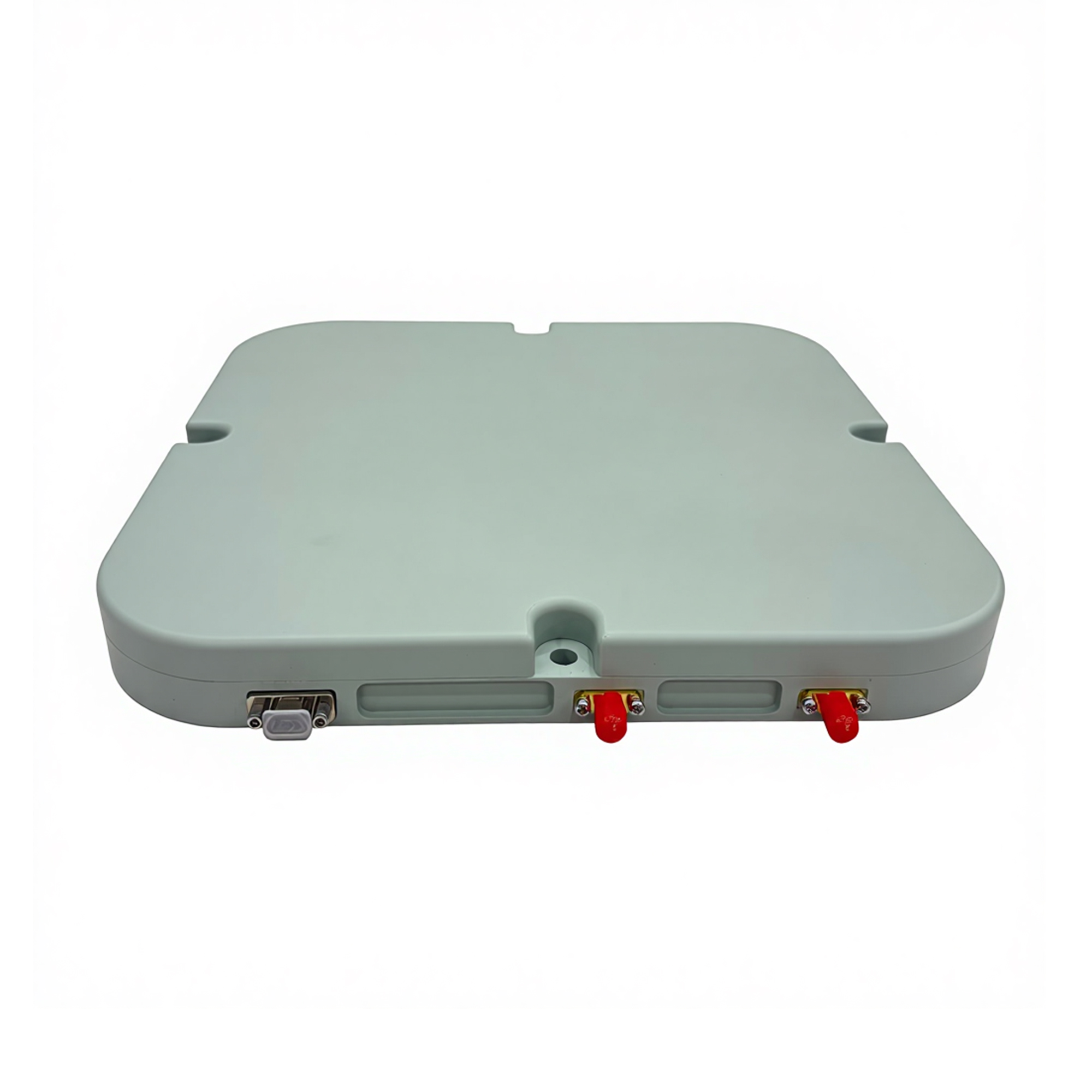
The physical composition of the antenna array dictates its defensive strength. The total number of internal antenna elements determines how many simultaneous interference sources the system can nullify. Engineers utilize a straightforward mathematical formula here.
An array with N elements can generate up to N-1 independent nulls. A basic system handles isolated threats. Complex arrays manage chaotic, multi-directional attacks simultaneously.
We typically encounter 4-element to 8-element arrays in tactical scenarios. A standard 4-element GNSS anti-jamming antenna provides three distinct spatial nulls. This configuration perfectly mitigates single or dual ground-based interference devices.
These baseline systems serve commercial fleets and lighter military airframes exceptionally well. They provide excellent suppression without demanding excessive power or massive physical footprints on the drone body.
Modern hostile environments involve highly coordinated, multi-directional attacks. Operators facing these scenarios need robust, scalable solutions. A 16-element anti-jamming antenna stands as the premier solution for these complex environments.
This advanced hardware suppresses up to 15 distinct interference vectors simultaneously. It neutralizes highly sophisticated RF attacks from multiple ground and aerial sources. It guarantees continuous absolute positioning in the most heavily contested airspace imaginable.
Airframe limitations firmly dictate your payload choices. Size, Weight, and Power (SWaP) remain paramount during hardware selection. Advanced CRPAs require significant power draws and feature substantial physical footprints. Operators must balance these demands against strict drone payload capacities.
Heavier antenna arrays reduce overall battery endurance. You must evaluate whether the increased defense capability justifies the shorter flight time. Always cross-reference the antenna weight against the maximum takeoff weight (MTOW) of your platform.
Array Complexity | Max Independent Nulls | Ideal UAV Category | Power Demand |
|---|---|---|---|
4-Element | 3 | Group 1 & 2 (Commercial/Light Tactical) | Low |
8-Element | 7 | Group 3 (Medium Altitude) | Moderate |
16-Element | 15 | Group 4 & 5 (Heavy/Strategic) | High |
Hardware Complexity and SWaP Trade-off Matrix
The Jamming-to-Signal (J/S) ratio defines ultimate survivability. You must clearly define the acceptable decibel threshold your systems must withstand. Higher J/S tolerance metrics guarantee operational continuity against closer, more powerful threats.
Look for hardware that promises significant J/S improvements over standard FRPA receivers. A robust system should deliver at least 40 to 80 dB of suppression depending on the interference bandwidth.
Single-point failures routinely ruin aerial missions. Your chosen hardware must fiercely protect multiple frequencies simultaneously. It should support L1, L2, and L5 bands natively. It must also remain entirely agnostic to specific constellations.
The receiver should cover GPS, Galileo, GLONASS, and BeiDou networks concurrently. This broad coverage ensures that if one frequency band suffers extreme interference, the system falls back onto alternative satellite networks seamlessly.
Active defense algorithms introduce inevitable microsecond delays. Complex anti-jam processing simply takes time to execute. These tiny latencies heavily impact high-speed UAV flight control loops.
Integration teams must accurately calibrate flight controllers to account for this minor processing delay. Failing to synchronize the data feeds can lead to micro-oscillations during fast autonomous flight profiles.
Antenna positioning drastically dictates operational success. You must mount the unit meticulously to prevent catastrophic self-interference. The drone's own telemetry transmitters, high-powered motors, and spinning carbon fiber props reflect signals constantly.
Poor placement ruins spatial filtering accuracy. If the antenna detects reflections from its own carbon fiber body, it may mistakenly nullify legitimate satellite vectors. You need a clear, unobstructed sky view and proper grounding.
Common Mistake: Mounting the CRPA too close to powerful onboard video transmitters.
Best Practice: Utilize dedicated RF absorber materials around the mounting base to minimize localized airframe reflections.
Hardware components must communicate flawlessly. You need seamless, high-speed data handoffs between the receiver unit and the primary flight controller. Ensure strict protocol compatibility before purchase.
Incompatible serial protocols or mismatched baud rates cause severe data loss during critical maneuvers. Verify that your defense hardware integrates smoothly with standard autopilots like Pixhawk or proprietary military flight computers.
Never rely solely on manufacturer spec sheets. Real-world conditions routinely reveal hidden hardware flaws. We strongly advocate for localized anechoic chamber testing during the initial validation phase.
Isolate the drone in an anechoic chamber to measure pure null depth.
Introduce simulated interference to observe receiver recovery times.
Conduct controlled open-air field tests against active transmitters safely.
Complete these rigorous steps before approving any fleet-wide rollout. This process proves your investment genuinely holds up under pressure.
Effective electronic warfare protection is no longer optional for mission-critical UAVs. Standard receivers simply cannot survive the dense interference present in modern operational environments. Operators must embrace advanced spatial filtering techniques to keep their fleets airborne.
Successful adoption completely hinges on matching your antenna array complexity to the specific threat environment. You must simultaneously respect the strict SWaP limitations of your chosen airframe. Balancing protection strength against payload capacity ensures maximum mission efficiency.
We recommend initiating a comprehensive SWaP-C (Size, Weight, Power, and Cost) feasibility assessment immediately. Request detailed integration schematics and localized testing data from vetted defense suppliers to secure your aerial assets today.
A: While spatial null-steering helps mitigate some signal anomalies, basic systems cannot block sophisticated spoofing. Specific anti-spoofing algorithms are required for full protection. These advanced defenses continuously monitor signal angle-of-arrival and utilize strict cryptography to verify authentic satellite signals before accepting the data.
A: Yes, generally. 16-element systems require a significantly larger physical footprint and demand a higher power draw. They are typically reserved for Group 3+ military and heavy industrial UAVs. Conversely, smaller Group 1 and Group 2 commercial drones usually rely on miniaturized 4-element arrays to manage weight restrictions.
A: An INS drifts naturally over time without external calibration. Terrestrial interference attacks successfully block the exact satellite data needed to correct this drift. Robust defense technology is absolutely necessary to protect the GNSS data link. This secure link continuously calibrates and corrects the INS during extended flights.


