
 News
News Views: 0 Author: Site Editor Publish Time: 2026-09-08 Origin: Site


Escalating electronic warfare (EW) threatens mobile platforms significantly today. Localized radio frequency (RF) interference actively disrupts vital tracking data. It aggressively degrades Position, Navigation, and Timing (PNT) reliability. This interference jeopardizes unmanned aerial vehicles (UAVs), unmanned ground vehicles (UGVs), and defense vehicles. Relying on standard receivers often causes catastrophic asset loss. Unverified hardware guarantees mission failure during intense GNSS denial events. Compromised autonomy becomes inevitable in these hostile environments.
We must address this critical vulnerability immediately. This article provides engineering and procurement teams an evidence-based framework. You will learn to evaluate and shortlist resilient navigation hardware effectively. We help you integrate an optimal anti-jamming antenna safely into your systems. You will accomplish this without violating strict platform constraints. You will also learn to look past exaggerated vendor claims. Engineering teams need this objective approach to ensure continuous, uninterrupted mobile navigation.
No solution offers 100% immunity; selection must focus on optimizing the Jamming-to-Signal (J/S) ratio threshold for specific operational environments.
Controlled Reception Pattern Antennas (CRPA) provide superior spatial filtering but require strict adherence to Size, Weight, Power, and Cost (SWaP-C) limits.
Multi-constellation support prevents single-point failure, making a hybrid GPS GLONASS anti-jamming antenna highly preferable for global deployments.
Validating vendor claims requires rigorous anechoic chamber testing and live-sky simulation, not just datasheet comparisons.
Transition the conversation from simple signal loss to severe operational liability. Unplanned positioning degradation stalls semi-autonomous systems completely. A drone drifting off course risks immense collateral damage. It also compromises the entire mission objective instantly. Planners must calculate the precise impact of sudden PNT deprivation. Relying on visual navigation alone is rarely sufficient. Inertial navigation systems drift rapidly without satellite correction updates. You must define the exact business and strategic liabilities of these failures.
You must establish strict success criteria for PNT resilience. Define baseline thresholds for acceptable navigation drift. Outline specific time-to-recovery metrics after jamming exposure. Demand continuous operation under various interference models. These models include continuous wave, narrowband, and broadband disruptions. Continuous wave interference targets single frequencies intensely. Broadband interference blasts noise across wide spectrums simultaneously. Your chosen hardware must handle these distinct attack vectors smoothly.
Skepticism remains absolutely vital during the procurement phase. Software-based receiver mitigations are definitely necessary. However, they remain highly insufficient alone. High-power proximity jammers easily overwhelm basic software filters. A hardware-level defense acts as your crucial first line of defense. Standard antennas simply cannot survive direct RF attacks. Upgrading your physical reception hardware prevents receiver saturation. This hardware upgrade keeps your internal software algorithms functioning correctly.
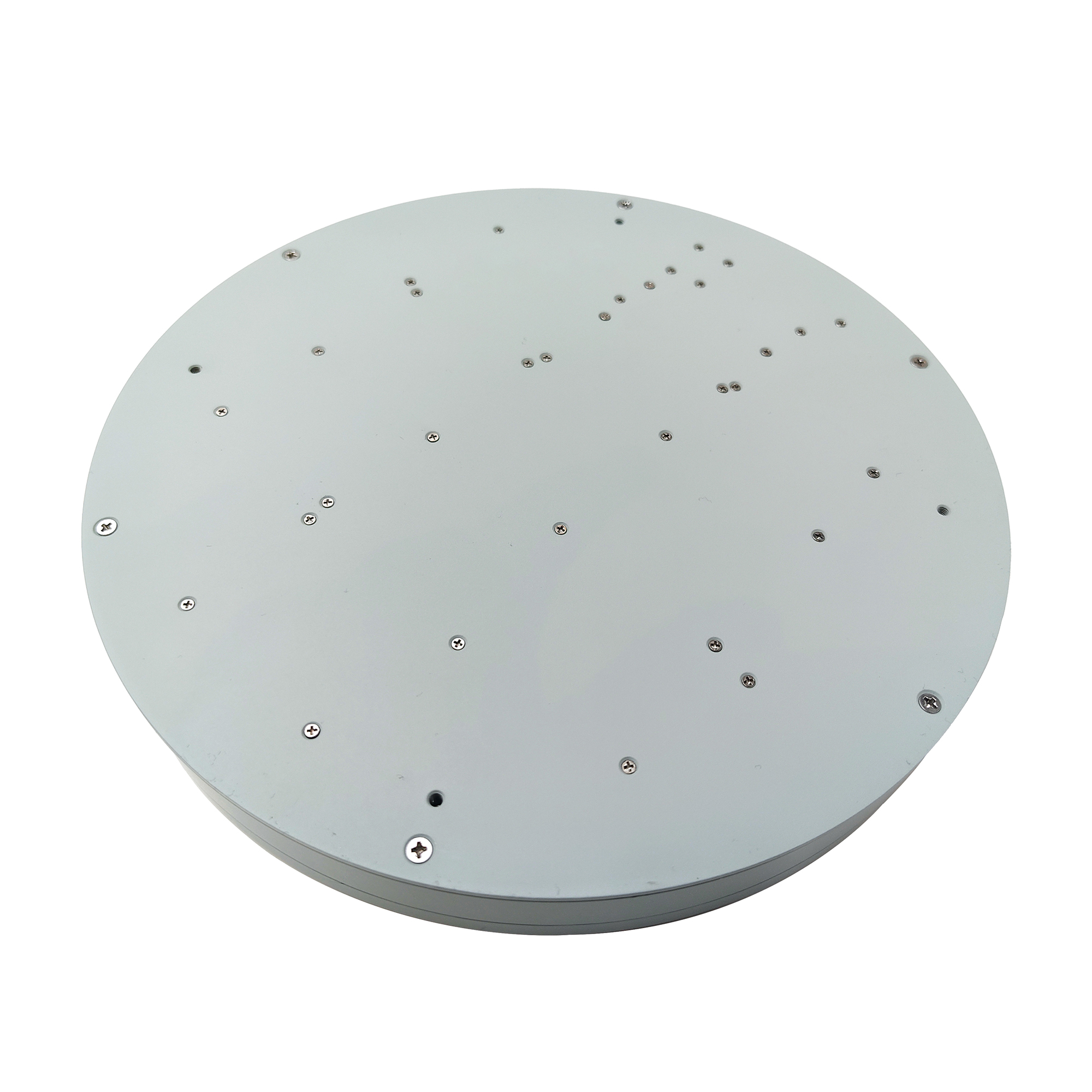
Evaluate different hardware categories carefully before making integration decisions. Advanced RF filtering uses a single-element design. It excises specific frequency spikes efficiently. This approach works best for accidental interference scenarios. Telecom bleed-over is a common example of accidental disruption. Single-element filters fit strict SWaP (Size, Weight, and Power) limits exceptionally well. However, significant operational limitations exist here. Single-element filters fail against broadband jamming. They cannot counter adaptive malicious attacks effectively. You need a more robust solution for hostile zones.
Controlled Reception Pattern Antennas (CRPA) provide maximum hardware defense. They utilize multi-element arrays to manipulate incoming signals dynamically. CRPAs create spatial nulls precisely in the jammer's direction. Engineers call this vital process Null-forming. It essentially blinds the antenna to the malicious source. CRPAs also focus signal gain directly toward active satellites via Beamsteering. This dual approach ensures a clean signal feed.
CRPAs are best suited for defense applications. Hostile EW environments demand this level of sophistication. Mission-critical autonomous navigation relies on a dedicated GNSS anti-jamming antenna entirely. However, CRPAs introduce notable design limitations. They demand higher power draw from the host platform. They also require a significantly larger physical footprint. Increased integration complexity is a major hurdle for compact mobile systems.
Table 1: Comparison of Single-Element and Multi-Element Architectures
Feature | Advanced RF Filtering (Single-Element) | CRPA (Multi-Element Array) |
|---|---|---|
Primary Mechanism | Frequency domain excision (Notch filtering) | Spatial domain filtering (Null-forming & Beamsteering) |
Best Use Case | Accidental interference, strict size constraints | Malicious EW environments, defense applications |
Jamming Threat Handled | Narrowband, single continuous wave | Broadband, adaptive, multiple dynamic jammers |
Physical Footprint | Small, lightweight, aerodynamic | Larger, heavier, requires complex mounting |
Define the exact Size, Weight, and Power allowances of your specific mobile platform. A solution ideal for a naval vessel will overload a Group 2 UAV easily. Large antennas drastically alter aerodynamics on smaller drones. They also disrupt the center of gravity. You must calculate power consumption impacts thoroughly. Battery-dependent mobile systems suffer under heavy electrical loads. CRPAs require internal processing units. These processors consume continuous power to calculate null steering algorithms. Balance survivability against your available power budgets carefully.
Best Practice: Always request exact idle and peak power consumption metrics from vendors. Ensure your platform's power distribution unit can handle the maximum draw during intense EW events.
Multi-constellation support is absolutely non-negotiable today. Evaluate the critical necessity of a comprehensive satellite system anti-jamming antenna carefully. Outdated GPS-only models create a dangerous single point of failure. Modern attackers target the L1 band aggressively. Relying on a single frequency invites disaster in contested environments.
Deploying a combined GPS GLONASS anti-jamming antenna offers massive systemic resilience. Support for Galileo and BeiDou constellations adds critical fallback options. If one frequency band is completely overwhelmed, alternate constellations maintain continuous tracking. Multi-frequency receivers hop across L1, L2, and L5 bands dynamically. This frequency diversity dilutes the jammer's overall effectiveness. Broadband jammers struggle to overpower all satellite frequencies simultaneously without revealing their exact location.
Assess dynamic response latency next during your evaluation. How quickly does the antenna array adapt to new threats? Moving jammers shift their attack angles constantly. Mobile navigation platforms also change orientation rapidly during evasive maneuvers. High-speed vehicles require millisecond adaptation rates. Slow nulling algorithms cause temporary signal dropouts. These dropouts confuse the internal navigation filters. A fast reaction time ensures continuous satellite lock during aggressive maneuvers.
Address the friction of hardware retrofitting directly. Legacy navigation receivers present unique integration challenges. Does the new antenna require a proprietary Antenna Control Unit (ACU)? Dedicated ACUs consume extra space and power. Fortunately, many advanced models process signals internally now. They output a clean, standard RF feed instead. This clean feed integrates easily into legacy systems. It bypasses the need for expensive receiver replacements.
Discuss the physical realities of mobile integration openly. Mounting location dictates overall performance heavily. Rotor blades chop incoming signals severely on helicopters and drones. Vehicle chassis structures create localized RF dead zones. Adjacent communication arrays cause severe multipath errors constantly. They block direct line-of-sight to the sky. You must map these obstructions carefully. Elevate the antenna above surrounding structural interference whenever possible.
Detail exact cable routing impacts on signal integrity. Cable length determines the rate of signal degradation. Poor shielding quality invites RF leakage directly into the line. Highlight potential signal degradation points during installation planning. Keep RF cable runs as short as possible. Use double-shielded coaxial cables strictly. Minimize the use of inline adapters. Every connection point introduces insertion loss. High insertion loss reduces the overall Jamming-to-Signal advantage.
Common Mistake: Routing sensitive RF antenna cables parallel to high-voltage motor wires. This setup induces electromagnetic interference (EMI) directly into the clean PNT feed, effectively jamming your own receiver.
Demand evidence-based metrics constantly during procurement. Reject generic marketing claims outright. Generic phrases like "interference-proof" mean nothing in engineering terms. Require vendors to provide specific J/S (Jamming-to-Signal) improvement data. This must be measured in decibels (dB). Request empirical data across multiple interference scenarios. Ask for test results against continuous wave and broadband noise. True performance is proven through hard data.
Outline industry standards for validation rigorously. Rely on trusted simulation frameworks for initial screening. Anechoic chamber results prove true spatial filtering capabilities. Chamber tests isolate the antenna from background RF pollution. They measure exact null depths accurately. MIL-STD environmental compliances guarantee physical durability. Look for specific certifications covering extreme vibration and temperature fluctuations.
Build your shortlisting logic using this structured decision tree:
Identify the primary operational threat profile you face (accidental telecom bleed-over vs. malicious state-level jamming).
Constrain your options by strict platform SWaP limits (weight, physical dimensions, maximum power draw).
Filter selections by required constellations and legacy receiver interoperability (RF output compatibility).
Validate performance claims through simulated hardware-in-the-loop (HIL) testing before final purchase.
Selecting the right navigation defense hardware is a delicate balancing act. You must align platform constraints against a realistic threat landscape. Ignoring physical limitations results in failed integrations. Ignoring the severity of modern RF threats leads to lost assets. A multi-element array offers unparalleled protection for critical missions. Single-element filters provide a lightweight alternative for less hostile zones.
Move your engineering teams beyond simple datasheet comparisons immediately. Define your maximum acceptable J/S ratio clearly. Initiate thorough Hardware-in-the-Loop (HIL) testing evaluations with your shortlisted vendors. Subject the hardware to simulated dynamic movements. Test it against multiple concurrent jammers. By following this objective framework, you ensure robust, reliable navigation for your entire mobile fleet.
A: Spoofing and jamming are technically different. Anti-jamming hardware prevents signal power overpowering. Spoofing involves deceiving the receiver with fake signals. While some advanced CRPA systems assist in spoofing detection via Direction of Arrival (DoA) algorithms, they cannot prevent it alone. Dedicated anti-spoofing software or encrypted receivers are still required to authenticate signals fully.
A: Not always. Many modern standalone CRPAs process the RF signal internally. They calculate the nulls and filter the interference onboard. They then output a clean, standard RF signal to legacy receivers. This plug-and-play capability minimizes retrofit costs and avoids complex receiver replacements.
A: Narrowband jammers often target specific frequencies like GPS L1 or L2. A multi-constellation system tracks multiple satellite networks simultaneously. It can seamlessly fall back on unaffected frequencies or alternate satellite signals from Galileo or BeiDou. This frequency diversity maintains continuous PNT even if one specific band is completely overwhelmed.


