
 News
News Views: 0 Author: Site Editor Publish Time: 2026-07-07 Origin: Site


Operational risks associated with RF interference are escalating rapidly across autonomous and critical infrastructure sectors. Standard GNSS signals travel thousands of miles from space, arriving at terrestrial receivers with incredibly low power levels. These weak signals are easily overpowered by low-cost, commercially available jamming devices. When vehicles or infrastructure lose Position, Navigation, and Timing (PNT) data, the resulting cascading failures introduce severe safety liabilities and operational downtime.
Relying on standard Fixed Reception Pattern Antennas (FRPA) leaves systems highly vulnerable in contested or high-interference environments. Migrating to advanced anti-jamming architectures is necessary to ensure operational continuity. By implementing robust hardware and software defenses, operators can maintain precise navigation and timing data even when subjected to targeted signal denial or heavy environmental noise.
Technology Shift: Transitioning to an active Controlled Reception Pattern Antenna (CRPA) is the most effective hardware-level defense against directional RF interference.
Dual Mitigation Vectors: Effective anti-jamming relies on a combination of spatial filtering (reducing gain toward interference) and digital beamforming (increasing gain toward authentic satellites).
Application-Specific Constraints: Selecting an anti-jamming antenna requires balancing Size, Weight, Power, and Cost (SWaP-C) against the required interference rejection capabilities, especially for UAV navigation antenna integration.
Spectrum Visibility: Modern systems must utilize real-time interference monitoring and spectral analysis to identify and mitigate jamming signals dynamically.
Implementation Reality: Anti-jamming systems mitigate signal denial but must be paired with anti-spoofing software and Inertial Navigation Systems (INS) for comprehensive PNT resilience.
A resilient PNT architecture requires continuous GPS tracking under duress, maintaining strict positioning accuracy and timing synchronization regardless of external RF noise. Baseline metrics for success involve the system's ability to hold satellite lock and provide uncorrupted coordinate data when exposed to specific decibel levels of interference. Field operators know that losing satellite lock for even a few seconds during a critical flight phase or automated docking procedure leads to immediate mission failure.
Interference falls into two primary categories. Malicious frequency-transmitting devices are intentionally designed to block or disrupt GNSS bands. Conversely, unintentional environmental interference stems from nearby radar installations, satellite communications, or urban multipath reflections. Both exploit the near-far problem. Because authentic satellite signals originate approximately 20,000 kilometers in space, they reach the earth's surface at roughly -130 dBm. Localized terrestrial transmitters, even those emitting only a few watts of power, easily drown out these faint signals.
To understand the threat landscape, we must categorize the interference sources encountered in the field:
Interference Type | Source Examples | Signal Characteristics | Impact on GNSS Receivers |
|---|---|---|---|
Intentional Jamming | Personal privacy jammers, military electronic warfare units | Continuous wave, swept continuous wave, broadband noise | Immediate loss of carrier-to-noise ratio, complete signal denial |
Unintentional Interference | High-voltage lines, heavy industrial machinery, broadcast towers | Harmonic emissions, out-of-band bleed-over | Intermittent signal degradation, increased positional error |
Multipath Reflections | Glass skyscrapers, water surfaces, metallic structures | Delayed signal arrival, phase shifts | Position drift, inaccurate timing synchronization |
Signal degradation directly compromises positioning accuracy and timing synchronization. Automated navigation protocols rely on continuous data streams to execute flight paths or routing logic. When interference surpasses the operational threshold, standard receivers lose lock on GNSS constellations entirely. This forces the system into dead reckoning mode, where accumulated drift rapidly degrades positional certainty until the vehicle can no longer operate safely. We see this frequently in drone operations where a sudden loss of GPS forces the flight controller into manual mode, often resulting in a crash if the operator is not prepared to take immediate control.
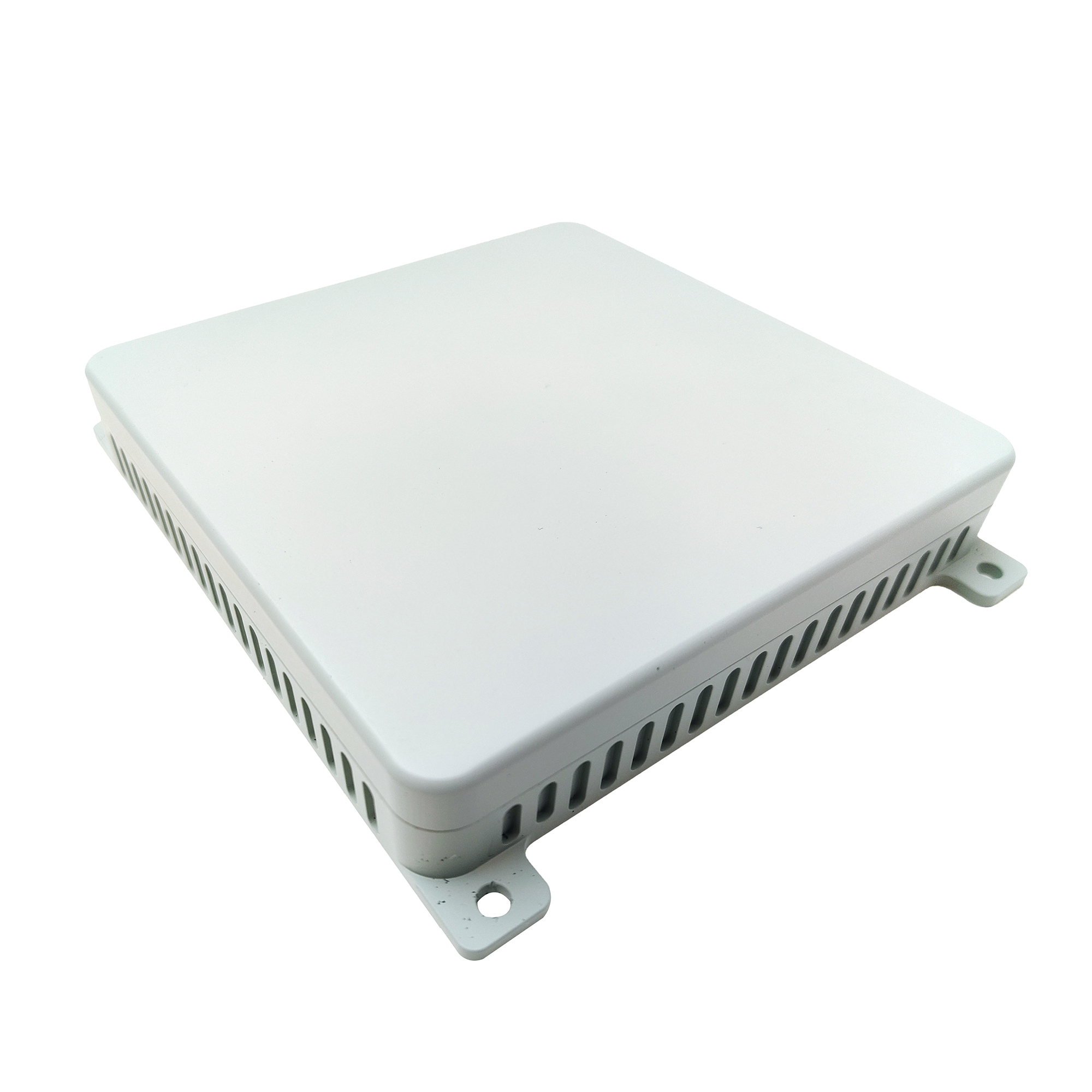
Maintaining continuous tracking requires specific hardware and software mechanisms. Modern solutions move beyond passive reception, actively manipulating how RF signals are processed before they reach the core GNSS receiver. The shift from passive to active antenna arrays represents a fundamental change in how we approach RF resilience.
The physical design of a CRPA antenna utilizes multiple antenna elements arrayed together on a single ground plane. Unlike legacy passive FRPA systems that receive signals uniformly from the sky, an active CRPA processes the phase differences of incoming signals across its multiple elements. This allows the system to determine the direction of arrival for both authentic satellite broadcasts and hostile jamming sources. The more elements an array has, the more distinct interference sources it can track and mitigate simultaneously.
Spatial filtering is the primary defense mechanism against high-power interference. Null steering dynamically adjusts the antenna's reception pattern to create attenuation blind spots, or nulls, directly in the path of the jamming source. This effectively ignores the noise. Beam steering, or beamforming, takes the opposite approach. Advanced arrays focus positive gain exclusively toward known, authentic satellites. This targeted reception maintains the necessary carrier-to-noise ratios required for continuous tracking.
The sequence of operations for a modern array typically follows these steps:
Signal Reception: Multiple elements receive incoming RF energy from all directions.
Direction of Arrival Calculation: The internal processor analyzes phase differences to locate the interference source.
Null Generation: The system electronically alters the reception pattern to place a deep null toward the jammer.
Beam Steering: The array simultaneously increases gain toward the calculated positions of GNSS satellites.
Continuous Monitoring: The system dynamically updates the nulls and beams as the vehicle moves or the jammer changes location.
Hardware arrays are driven by real-time interference monitoring and mitigation algorithms. Techniques like adaptive notch filtering and spectral analysis visualize and isolate complex waveforms in the RF environment. Integrating digital signal processing directly inside the anti-jamming antenna enclosure reduces processing latency, allowing the system to react to dynamic jamming threats in milliseconds. This tight integration prevents the core receiver from ever processing the corrupted RF data.
Selecting the correct hardware requires mapping specific antenna features to operational outcomes and vehicle types. Environmental conditions and payload limitations dictate the necessary specifications. You cannot simply bolt a heavy marine array onto a lightweight drone and expect optimal performance.
Drone platforms operate under strict Size, Weight, and Power (SWaP) constraints. A heavy, power-hungry array will severely reduce flight time. Selecting a compact UAV navigation antenna involves finding the exact balance between physical footprint and the number of internal elements needed for effective null steering. Engineers must calculate the aerodynamic drag introduced by the radome and ensure the power draw does not overtax the flight battery.
Different flight profiles face distinct RF threats. Agricultural drone protection focuses heavily on mitigating unintentional RF interference. Heavy farm machinery, high-voltage power lines, and rural telecommunications infrastructure frequently disrupt L-band signals. Delivery UAV protection requires defense against urban canyon multipath rejection, signal reflections from glass buildings, and intentional localized jamming devices often found in populated delivery zones.
Beyond Visual Line of Sight (BVLOS) operations require maximum signal redundancy. Long-range inspection drone protection relies on multi-frequency and multi-constellation support. By tracking GPS, GLONASS, Galileo, and BeiDou across L1, L2, and L5 bands simultaneously, the system ensures that if one frequency is jammed, the vehicle maintains navigation through alternative satellite networks. This redundancy is non-negotiable for pipeline inspections or border patrol routes.
Maritime environments present unique signal challenges. Multi-path reflections off the water surface confuse standard receivers. Furthermore, marine vessels feature high-vibration deck environments and operate alongside high-power naval radars or SATCOM uplinks. Antennas deployed here require robust ingress protection and specialized filtering to ignore onboard transmission equipment. Salt fog corrosion resistance is also a mandatory specification for any marine-grade array.
Evaluating manufacturers requires a strict technical framework based on empirical performance metrics and integration capabilities. Relying on marketing brochures leads to field failures. You must demand hard data.
The primary metric for a GPS anti-jamming antenna is its Jamming-to-Signal (J/S) ratio. This defines the maximum power level of interference the system can withstand while still maintaining satellite lock. Buyers must evaluate the manufacturer's stated mitigation limits, expressed in decibels, against the expected threat levels in their operational environment. A system offering 40 dB of rejection might survive unintentional noise, but surviving a targeted attack often requires 80 dB or more.
Commercial Off-The-Shelf (COTS) systems offer accelerated deployment timelines and standardized integration protocols. Highly customized military-grade antenna arrays provide superior J/S tolerance and element counts but require extensive engineering cycles and higher power budgets. For most commercial autonomous operations, a high-end COTS solution provides the necessary resilience without the extreme lead times of custom builds.
An anti-jamming GNSS unit rarely operates in isolation. It must pair seamlessly with existing GNSS receivers and Inertial Navigation Systems. Deep coupling or tight coupling architectures fuse the inertial sensor data with the GNSS tracking loops, allowing the receiver to hold satellite lock longer during severe interference events. This sensor fusion bridges the gap during momentary signal outages.
International procurement is heavily regulated. Buyers must navigate ITAR regulations and dual-use export controls when sourcing advanced arrays. Additionally, systems integrated into commercial airspace must adhere to strict aviation standards, such as DO-384, to guarantee performance and safety compliance. Failing to account for these regulations during the design phase will halt production entirely.
Deploying active antenna technology introduces specific operational trade-offs that engineering teams must address during the design phase. Ignoring these realities leads to compromised vehicle performance.
Active antenna arrays and integrated digital processing units draw continuous power. This impacts flight times and operational battery budgets on smaller vehicles. Engineers must calculate the exact power draw of the anti-jamming system and adjust payload capacities accordingly. Every watt consumed by the antenna is a watt taken away from propulsion or primary sensors.
Spatial filtering prevents raw signal denial by blocking high-power noise. However, mitigating sophisticated spoofing attacks—where false coordinate data is broadcast at normal power levels—requires different defenses. Full UAV protection requires pairing the hardware array with cryptographic signal authentication and specialized anti-spoofing software. The antenna filters the noise, but the software must verify the authenticity of the remaining signals.
Validating antenna performance prior to deployment is mandatory. Teams should utilize RF hardware-in-the-loop (HIL) simulators and anechoic chambers to subject the hardware to controlled interference. Field testing with authorized jamming equipment verifies the system's dynamic response in real-world conditions. Never deploy an untested array into a critical operational environment.
Advanced anti-jamming features are a critical necessity for any autonomous or critical system relying on continuous GPS tracking. Without active spatial filtering and beamforming, vehicles remain highly susceptible to both intentional disruption and environmental noise. To secure your navigation architecture, follow these immediate steps:
Audit your current PNT vulnerabilities by mapping the expected RF interference levels in your operational zones.
Define your strict Size, Weight, and Power (SWaP) constraints before evaluating any hardware arrays.
Calculate your required Jamming-to-Signal (J/S) ratio based on worst-case interference scenarios.
Request empirical simulation reports and anechoic chamber test data from shortlisted antenna manufacturers.
Integrate the selected array with a robust Inertial Navigation System (INS) to ensure complete sensor fusion.
A: A standard GPS antenna uses passive, omnidirectional reception, making it vulnerable to noise from any direction. An anti-jamming antenna uses active, directional signal filtering, null steering, and beam steering across multiple elements to block interference and focus on legitimate satellites.
A: It uses multiple physical elements to calculate the direction of arrival for incoming interference. The internal processor then electronically blocks that specific vector while optimizing reception vectors for legitimate satellite signals.
A: Null steering creates zero-gain points, or blind spots, directly towards the source of the interference. Beamforming actively increases the antenna's gain in the precise direction of known, legitimate satellites to boost signal strength.
A: Spatial filtering helps ignore off-angle fake signals, but it is not a complete solution. Spoofing involves faking signals rather than just blocking them. Full protection requires dedicated anti-spoofing algorithms and cryptographic tracking software.
A: SWaP stands for Size, Weight, and Power. UAVs have strict limitations on physical footprint, aerodynamic drag, payload weight, and battery draw. Antennas must be compact and lightweight to avoid reducing the drone's operational flight time.
A: Effectiveness is tested using multi-channel GNSS simulators and anechoic chambers to create controlled interference environments. Authorized, field-based dynamic jammer validation is also used to measure the exact Jamming-to-Signal (J/S) tolerance during physical movement.


