
 News
News Views: 0 Author: Site Editor Publish Time: 2026-07-21 Origin: Site


The commoditization of software-defined radios (SDRs) has escalated GPS spoofing from a specialized military threat to a pervasive risk in commercial and tactical environments. Geopolitical spillover frequently disrupts civilian transport corridors, turning reliable positioning into a high-stakes vulnerability. Standard GNSS receivers inherently trust incoming signals. They remain unable to distinguish between authentic satellite broadcasts and localized counterfeit signals. This fundamental flaw leads to catastrophic navigation failures, hijacked routes, and compromised autonomous systems without triggering standard loss-of-signal alarms.
Mitigating these vulnerabilities requires moving beyond basic software-based anomaly detection. Upgrading to a hardware-level anti-interference antenna is the only verifiable method to ensure secure navigation in contested airspace and high-stakes operations. By physically filtering RF signals, these advanced antenna systems block malicious interference before it corrupts the receiver's positioning data. We will examine the mechanics of signal deception and how specialized antenna upgrades neutralize these threats to protect critical field operations.
Hardware Over Software: While software algorithms can flag anomalies, only physical RF filtering via an anti-interference antenna can actively block counterfeit signals before they reach the receiver.
Spatial Filtering is Critical: Multi-element antenna arrays (CRPAs) defeat spoofing by creating RF "nulls" directed at the interference source while maintaining line-of-sight with authentic satellites.
The Danger of "Silent" Spoofing: Unlike blunt jamming, spoofing introduces Hazardously Misleading Information (HMI) that silently hijacks receivers without triggering traditional fail-safes.
SWaP-C Dictates Feasibility: Selecting the right anti-jamming module requires balancing Size, Weight, Power, and Cost against the specific payload constraints of the platform.
Sensor Fusion is Mandatory: True resilience requires pairing anti-interference hardware with Inertial Navigation Systems (INS) to maintain positioning during total RF denial.
Establishing a robust defense architecture requires understanding the baseline vulnerabilities of legacy systems. Standard GNSS technology was designed for benign environments, making it highly susceptible to modern electronic warfare (EW) tactics. When you deploy a standard patch antenna in a contested zone, you are essentially flying blind against adversaries equipped with off-the-shelf SDRs. We need to break down exactly why these legacy systems fail when subjected to targeted RF manipulation.
GNSS signals transmit from Medium Earth Orbit (MEO), roughly 20,000 kilometers above the Earth's surface. By the time these signals reach a ground-based or airborne receiver, they arrive with extremely low power, typically around -160 dBW. To put this into perspective, the signal strength is roughly equivalent to viewing a 25-watt light bulb from 10,000 miles away. This faint signal strength makes them incredibly easy to overpower with terrestrial transmitters. Furthermore, civilian L1 and L2 signals lack cryptographic authentication. The signal structure is public knowledge, documented in interface control documents (ICDs) available to anyone with an internet connection.
This design flaw forces legacy receivers to lock onto the strongest available signal matching the expected structural characteristics. The receiver's tracking loops—specifically the phase-locked loop (PLL) and delay-locked loop (DLL)—are programmed to correlate incoming RF energy with internally generated replica codes. When a stronger signal presents the correct pseudo-random noise (PRN) code, the tracking loops naturally gravitate toward it. They do not verify the origin of the transmission; they only verify the math.
Cheap SDRs exploit this vulnerability by cloning the PRN codes of authentic GPS signals. These devices broadcast counterfeit signals at a slightly higher power level than the genuine satellite transmissions. The unshielded receiver naturally drops the authentic satellite track and locks onto the stronger, fabricated signal. Once the receiver accepts the counterfeit signal, the attacker controls the calculated Position, Velocity, and Time (PVT) solution. This is not a theoretical vulnerability; it is a daily operational reality in conflict zones and border regions.
To illustrate the disparity, consider the power levels involved in typical GNSS operations versus localized interference:
Signal Source | Typical Power Level at Receiver | Distance from Receiver | Authentication Mechanism |
|---|---|---|---|
Authentic GPS L1 (MEO) | -160 dBW to -158 dBW | ~20,000 km | None (Civilian) / M-Code (Military) |
Commercial 1W Jammer | -90 dBW to -60 dBW | 1 km to 10 km | N/A (Noise) |
SDR Spoofer (Directional) | -150 dBW to -130 dBW | 100 m to 5 km | Cloned PRN Codes |
Understanding the distinction between jamming and spoofing is critical for implementing effective countermeasures. Field operators often use the terms interchangeably, but the mitigation strategies require entirely different hardware approaches.
Jamming is a brute-force denial of service attack. It involves broadcasting high-power RF noise across the GNSS frequency bands to drown out the faint satellite signals. When a receiver encounters a jamming environment, the signal-to-noise ratio (SNR) plummets. The tracking loops lose their lock on the satellites, causing an immediate loss of positioning data. While disruptive, jamming is loud and obvious. The receiver triggers loss-of-signal alarms, alerting operators to the interference so they can switch to alternative navigation methods or initiate dead-reckoning protocols.
Spoofing, on the other hand, is a deception attack. It is the gradual, coherent injection of counterfeit Position, Navigation, and Time (PNT) data. GPS spoofing is far more dangerous because it is a "silent" hijacking. Advanced spoofers do not blast the receiver with noise. Instead, they transmit cloned signals that perfectly match the timing and Doppler shift of the authentic satellites currently in view. The spoofer matches the real power levels and then slowly increases the transmission power by a fraction of a decibel. This subtle overpowering steers the receiver's tracking loops away from genuine coordinates without triggering any loss-of-signal alerts.
The operational impact of Hazardously Misleading Information (HMI) is severe. For autonomous vehicles and delivery & logistics operations, spoofing can silently reroute commercial drones to unauthorized landing zones. Ground vehicles can be steered off course into hazardous terrain, all while the system's internal diagnostics report normal operation. The vehicle's flight controller or navigation computer believes it is exactly where it is supposed to be, making software-based fail-safes useless.
Electronic Warfare in regional conflict zones frequently bleeds into civil airspace. High-powered military jammers and spoofers deployed in areas like Eastern Europe, the Baltic region, and the Middle East inadvertently affect civilian systems hundreds of miles away. RF energy does not respect national borders. A high-gain directional spoofer aimed at a tactical drone can easily intersect commercial flight paths or maritime shipping lanes.
This geopolitical spillover exposes the systemic vulnerability of commercial shipping, aviation, and critical infrastructure that rely on unshielded GNSS receivers. Commercial airliners frequently report losing GPS lock or receiving false positioning data while flying over the Mediterranean or near the Black Sea. Maritime vessels experience sudden jumps in their AIS (Automatic Identification System) reported positions, showing ships supposedly located miles inland. Without robust hardware protection, these sectors face significant operational risks, increased fuel consumption due to rerouting, and severe safety hazards.
The reliance on unauthenticated civilian GNSS signals has created a massive attack surface. Upgrading the physical antenna infrastructure is no longer an optional enhancement for military assets; it is a mandatory requirement for any operation that depends on accurate, uninterrupted PNT data in the modern RF environment.
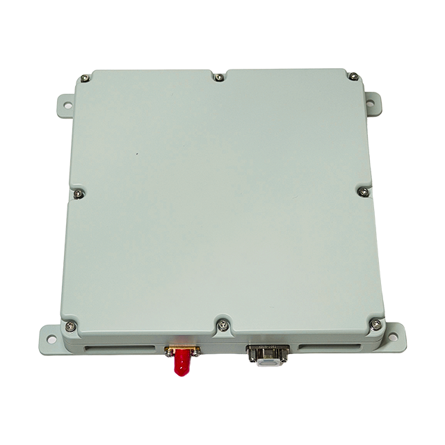
To secure critical operations, organizations must deploy hardware mechanisms that physically separate authentic signals from malicious ones. Software patches cannot fix a saturated RF front-end. An anti-interference antenna provides the necessary physical layer of defense, acting as a spatial filter that discriminates signals based on their angle of arrival rather than just their code structure.
A Controlled Reception Pattern Antenna (CRPA) utilizes a multi-element antenna array to dynamically alter its reception pattern. This physical architecture is essential for robust UAV protection and secure navigation in contested environments. Unlike a standard patch antenna that has a fixed, hemispherical reception pattern, a CRPA consists of multiple individual antenna elements (typically 4, 7, or 8 elements) arranged in a specific geometric configuration on a single ground plane.
The core mechanism behind a CRPA is spatial filtering and null steering. The antenna array is connected to a specialized processing unit that continuously monitors the RF environment. When a signal hits the array, it arrives at each individual element at a slightly different time due to the physical spacing between them. By measuring these minute phase differences, the processor calculates the precise angle of arrival (AoA) of the incoming signal.
Authentic GNSS signals arrive from satellites moving in predictable orbital trajectories overhead. Spoofed signals and jamming noise typically originate from terrestrial sources—ground vehicles, towers, or low-flying drones. When the CRPA detects a high-power signal originating from the horizon or a static terrestrial location, it identifies it as malicious. The processor then dynamically adjusts the phase and amplitude weights of the signals from each antenna element before combining them. This mathematical combination creates destructive interference in the specific direction of the threat, effectively forming a physical "null" or blind spot in the antenna's reception pattern.
Simultaneously, advanced CRPAs utilize beamforming techniques. While null steering reduces gain in the direction of the jammer, beamforming actively amplifies signals coming from known satellite locations. This digital beam steering ensures the receiver maintains a strong connection to authentic GNSS data while completely discarding ground-based spoofing sources. The result is a clean, uncorrupted RF feed delivered to the GNSS receiver, even when surrounded by multiple high-power jammers.
Antenna Type | Reception Pattern | Interference Mitigation | Primary Use Case |
|---|---|---|---|
Standard Patch Antenna | Fixed Hemispherical | None (Relies on receiver software) | Benign environments, consumer devices |
Choke Ring Antenna | Fixed, Multipath Rejection | Passive (Blocks low-elevation signals) | Surveying, reference stations |
CRPA (4-Element) | Dynamic Null Steering | Active (Creates up to 3 nulls) | Tactical UAVs, ground vehicles |
CRPA (8-Element) | Null Steering + Beamforming | Active (Creates up to 7 nulls, boosts satellites) | Critical infrastructure, military aviation |
While spatial filtering handles directional threats, advanced analog hardware filtering plays a crucial role in blocking out-of-band and narrow-band RF interference before the signal is digitized. The RF front-end of an anti-interference antenna incorporates highly selective Surface Acoustic Wave (SAW) filters and robust Low Noise Amplifiers (LNAs). These components act as the first line of defense against brute-force jamming.
Bandpass and notch filters eliminate unwanted frequencies, ensuring only the intended GNSS bands reach the receiver processing unit. If a nearby communications transmitter or radar system bleeds into the GPS L1 band, a high-quality SAW filter will attenuate that out-of-band noise, preventing the LNA from becoming saturated. Saturation is a critical failure mode; if the LNA is overwhelmed by a strong out-of-band signal, it cannot amplify the weak GNSS signals, leading to a complete loss of tracking.
Multi-frequency tracking provides an additional layer of hardware resilience. Modern anti-interference antennas are designed to process signals across multiple bands, including L1, L2, and L5 for GPS, as well as corresponding bands for GLONASS, Galileo, and BeiDou. If a spoofer targets a single frequency—for example, flooding the L1 band with counterfeit data—the system can fall back to uncompromised bands like L2 or L5. This frequency diversity significantly complicates the attacker's task. To successfully hijack a multi-frequency receiver, the adversary must simultaneously spoof multiple frequencies across different bands with perfect timing synchronization, a task that requires exponentially more complex and expensive EW equipment.
Many legacy system operators attempt to mitigate spoofing through software updates alone. Software-only spoofing detection relies on monitoring automatic gain control (AGC) fluctuations, analyzing sudden clock drift, or cross-checking the PVT solution against expected vehicle dynamics. While these algorithms can flag potential anomalies and alert the operator, they cannot physically prevent the counterfeit signal from entering the receiver.
Once the RF front-end is saturated by a spoofer, the receiver's tracking loops are compromised. Software mitigation becomes ineffective because the underlying data feeding the algorithms is entirely fabricated. You cannot compute your way out of a saturated RF front-end.
An inline anti-jamming module combined with intelligent software algorithms creates a hybrid hardware-software approach. The hardware physically blocks the interference through null steering and spectral filtering, ensuring only clean RF energy reaches the digitizer. The software then provides continuous monitoring, system integrity checks, and sensor fusion management. This comprehensive defense strategy ensures continuous, reliable navigation even in highly contested RF environments where software alone would fail immediately.
Deploying an anti-interference antenna is not a simple plug-and-play operation. Field integration requires careful consideration of the platform's physical constraints and the operational environment. You must evaluate how the hardware interacts with the vehicle's existing avionics, power systems, and structural layout.
Selecting the right anti-jamming module requires a strict evaluation of Size, Weight, Power, and Cost (SWaP-C). A massive 8-element CRPA designed for a naval destroyer cannot be mounted on a Group 2 tactical drone. The physical footprint of the antenna array directly impacts the aerodynamic profile of the vehicle, while the processing unit draws power from the platform's limited reserves.
For small UAVs and autonomous delivery vehicles, engineers must select compact 4-element arrays that offer a balance between nulling capability and payload impact. These smaller systems typically draw less than 10 watts of power and weigh under a kilogram, making them suitable for battery-operated platforms. However, they are limited in the number of simultaneous jammers they can null (usually up to three). For larger ground vehicles or manned aircraft, where SWaP constraints are less rigid, 7-element or 8-element arrays provide superior protection, capable of nulling multiple dynamic threats while simultaneously beamforming toward authentic satellites.
Even the most advanced CRPA can be overwhelmed if an adversary deploys enough jammers to surround the platform, exceeding the array's degrees of freedom. True resilience requires pairing anti-interference hardware with an Inertial Navigation System (INS). This sensor fusion approach guarantees continuous PNT data during periods of total RF denial.
An INS relies on internal accelerometers and gyroscopes to calculate position through dead reckoning. It does not require external RF signals, making it immune to jamming and spoofing. However, INS sensors suffer from drift over time. The integration strategy involves using the clean, authenticated GNSS data provided by the anti-interference antenna to continuously calibrate the INS. If the vehicle enters an EW environment so severe that the CRPA cannot maintain a satellite lock, the system seamlessly falls back to the INS. Because the INS was freshly calibrated by the protected GNSS feed right up until the moment of denial, it can maintain accurate positioning for an extended duration until the vehicle exits the contested zone.
Protecting critical infrastructure and autonomous systems requires proactive hardware upgrades against escalating RF threats. Implement these action-oriented steps to secure your navigation systems:
Conduct a comprehensive RF vulnerability assessment of your current GNSS infrastructure to identify specific exposure points to terrestrial spoofing and jamming.
Replace legacy patch antennas with multi-element CRPA anti-interference arrays to establish physical spatial filtering against directional threats.
Configure your receivers to utilize multi-frequency tracking across L1, L2, and L5 bands to ensure automatic fallback during targeted single-band interference.
Integrate your anti-jamming hardware directly with a tactical-grade Inertial Navigation System (INS) to maintain accurate dead-reckoning positioning during total RF denial.
A: Jamming uses high-power RF noise to drown out GPS signals, causing an immediate loss of service and triggering alarms. Spoofing involves transmitting counterfeit signals to silently deceive the receiver into calculating a false position or time without alerting the operator.
A: A Controlled Reception Pattern Antenna (CRPA) uses a multi-element array to detect the angle of arrival of incoming signals. It dynamically alters its reception pattern to create RF "nulls" in the direction of the interference, physically blocking the spoofed signal.
A: No. While software can detect anomalies like sudden clock drift, it cannot prevent a strong counterfeit signal from saturating the receiver's RF front-end. Hardware-level filtering is required to physically block the interference before digitization.
A: Multi-frequency tracking provides critical redundancy. If an attacker successfully spoofs or jams one frequency band, the receiver can automatically rely on the uncompromised bands to maintain accurate positioning and timing data.
A: An INS provides dead-reckoning navigation based on internal accelerometers and gyroscopes. It allows the system to maintain accurate positioning during total RF denial when even advanced anti-jamming antennas are temporarily overwhelmed.


